Behringer 2600
Init patchs
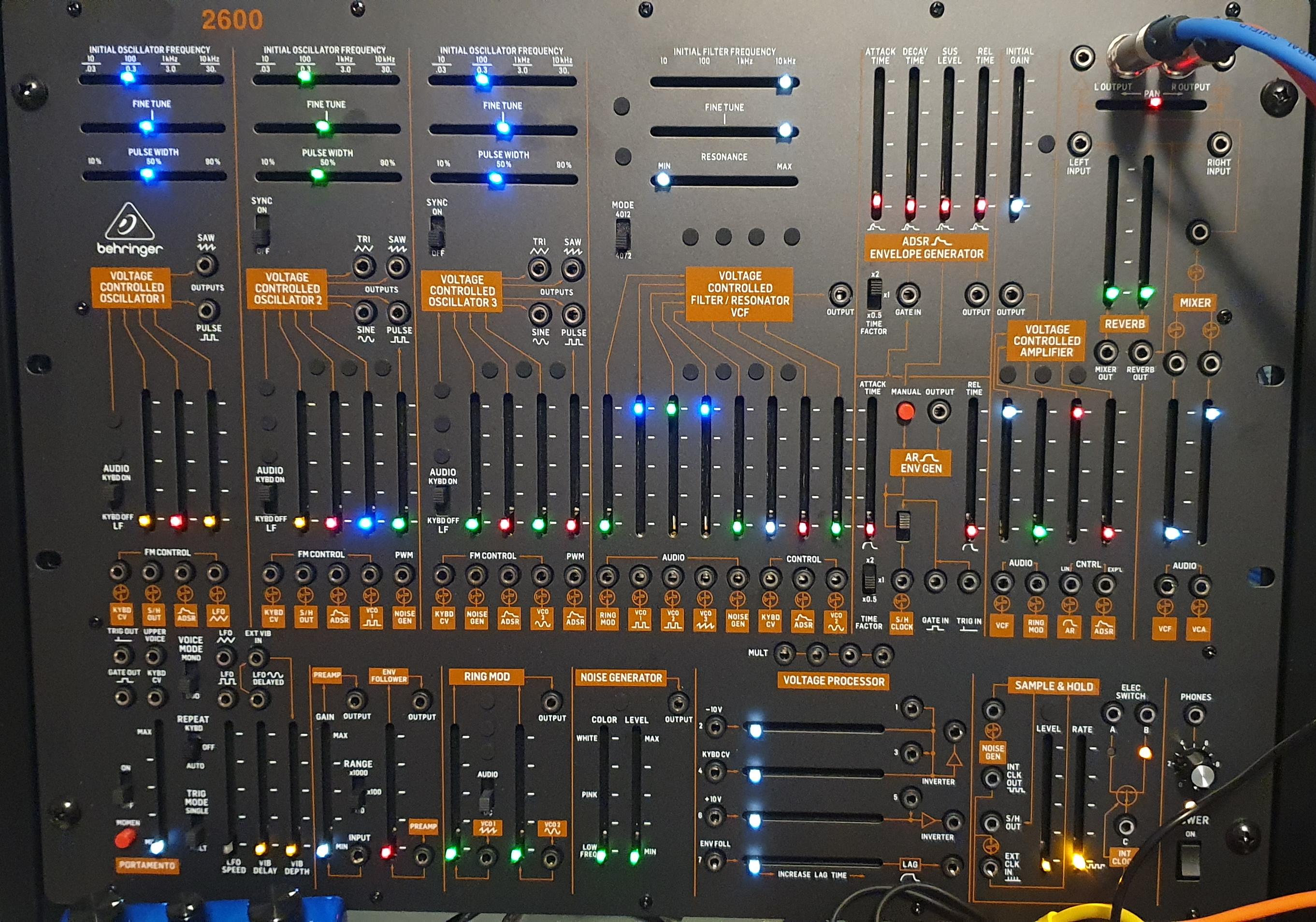 init patch with 3 osc
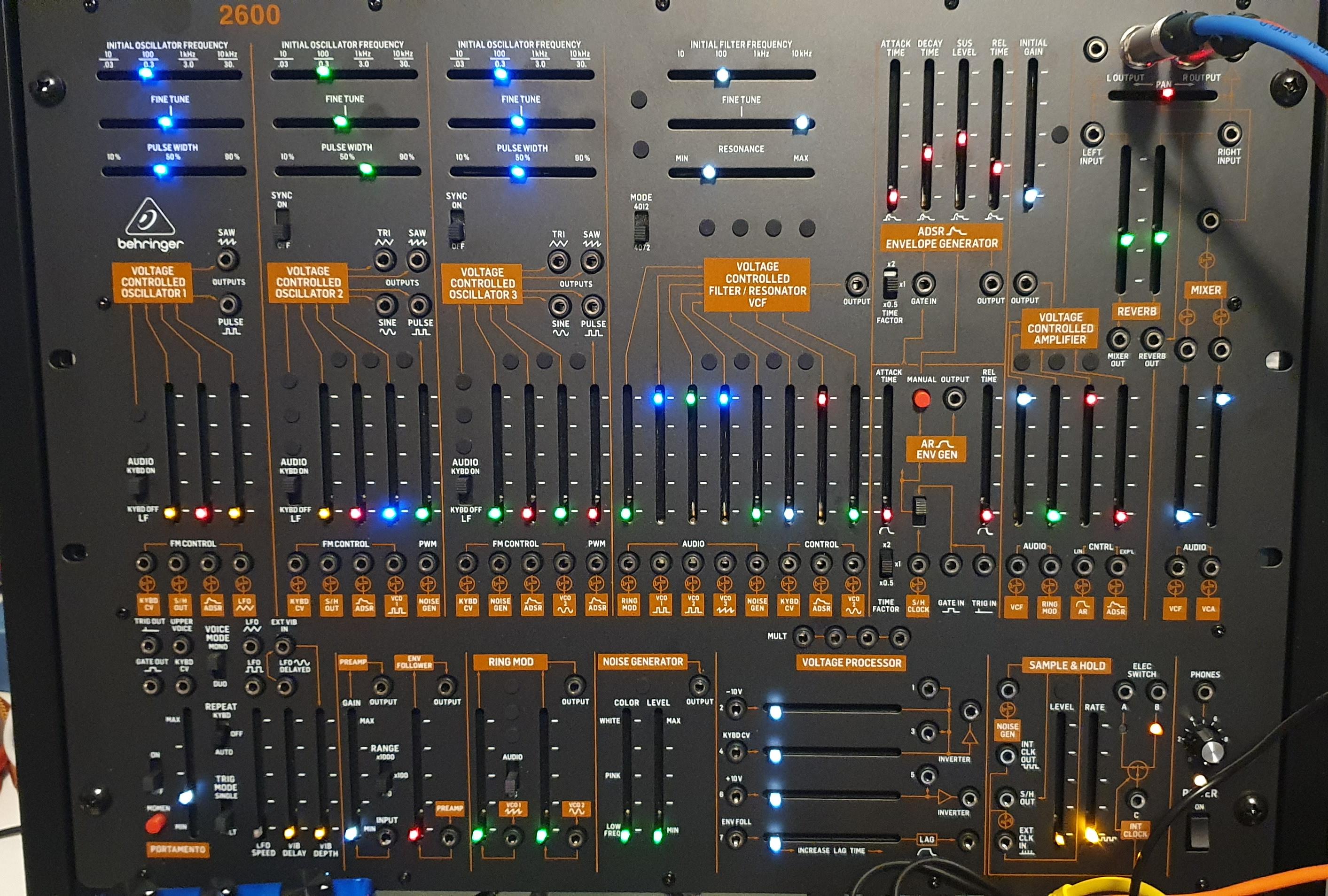 with filter envelope
Tips
L-R Panning
We need 2 signals, one going up, the other going down.
OSC1 is the modulation source. OSC1 must be set as LFO.
OSC3 is the sound source.
The RING MOD is used as a VCA. RING MOD is in DC mode.
Left sound level is controlled with Ring Mod level.
Right sound level is controller with VCA "VCF Input" level.
Internal reverb is by-passed.
graph LR
    A((VCO1 SAW)) --cv--> B(Mult)
    B(Mult) --cv--> C(Ring Mod)
    D((VCO3)) ==audio==> C(Ring Mod)
    C(Ring Mod) ==audio==> L(Left out)
    B(Mult) --cv--> E(Inverter)
    E(Inverter) --cv--> F(VCA)
    F(VCA) ==audio==> R(Right out)
    D((VCO3)) ==audio==> G(VCF)
    G(VCF) ==audio==> F(VCA)
High Pass & Band Pass filters
Principle: invert the VCF output and mixes it with the original signal. Some signal therefore cancel out and what pass through is what could
not pass through the filter.
Mix and balance are important.
- OSC1 --> VCF --> VCA
- OSC1 --> invert --> VCA
Mix and balance the inverted and non-inverted signals to maximise cancellation.
The RING MOD (DC mode) input of the VCA is an inverted input. So we can use this directly and avoid passing through an inverter:
- OSC1 --> VCF (normaled) --> VCA (normaled)
- OSC1 --> VCA RING MOD
Use the MULT to filter 2 osc.
Modulated high-pass filter
graph LR
    LFO --cv--> MULT
    MULT --cv--> VCF
    MULT --cv--> RingMod
    OSC3 ==audio==> VCF
    OSC3 ==audio==> RingMod
    VCF ==audio==> VCA
    RingMod ==audio==> VCA
Turn up RING MOD level in the VCA to go from a LPF to a resonant HPF.
RING MOD is in DC mode.
High-pass filter
graph LR
    OSC ==> VCF
    OSC ==> VCA-RingMod
    VCF ==> VCA
Band-pass filter
https://www.youtube.com/watch?v=Nm7t3jQaOBc
graph LR
    OSC ==> VCF
    VCF ==> vca(VCA VCF)
    vca(VCA VCF) ==> VCA
    VCA-RingMod ==> VCA
    OSC ==> VCA-RingMod
    VCF ==> Volt-Proc
    VCA ==> Volt-Proc
    Volt-Proc ==> inverter-as-mixer
    inverter-as-mixer ==> Mixer-VCA
Notch filter
graph LR
    OSC ==> VCF
    VCF ==> VCA-VCF
    VCA-VCF ==> VCA
    VCA-RingMod ==> VCA
    OSC ==> VCA-RingMod
    VCF ==> Volt-Proc
    VCA ==> Inverter
    Inverter ==> Volt-Proc
    Volt-Proc ==> inverter2
    inverter2 ==> Mixer-VCA
Blips blips
Triggering
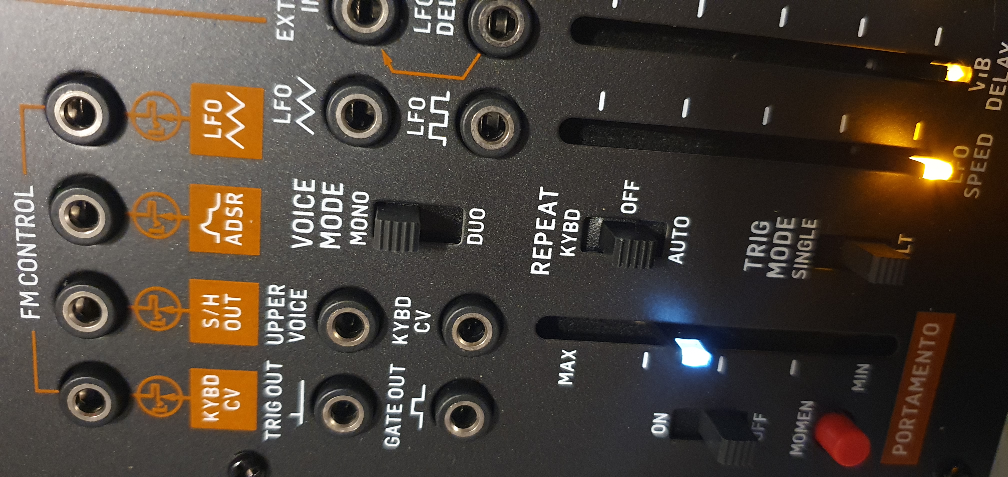
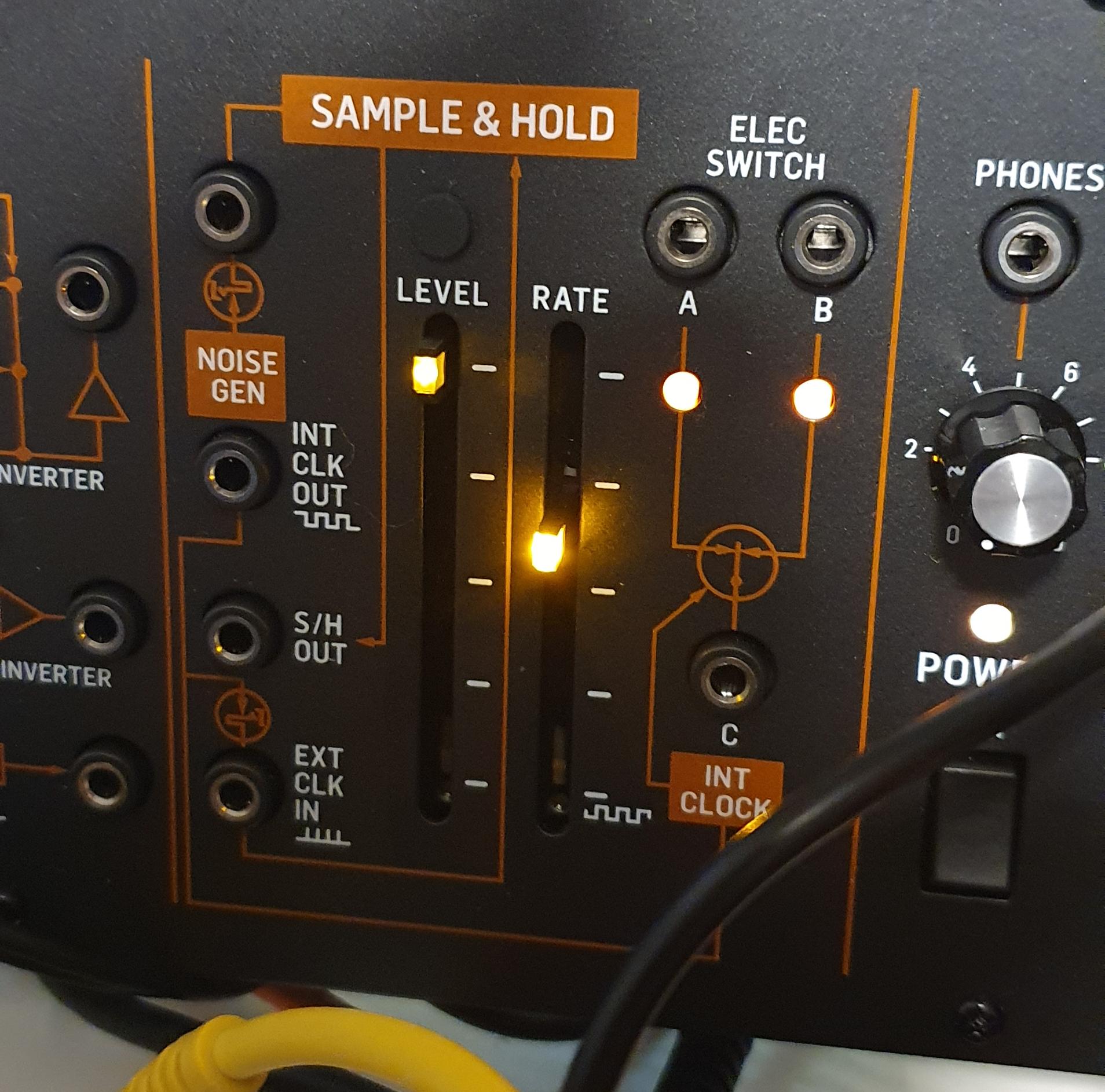
Use the S/H Gate input with the switch in down position. Otherwise, one need to use both Gate and Trig inputs.
From https://community.musictribe.com/discussions/172634/310727/2600-gate-trigger-issues :
I have received a response from Thomann support regarding this problem with a different and the really correct way to trigger both envelopes with a single gate signal in a way, that triggers the attack of the ADSR as expected. The gate signal should be patched into "S&H clock" (22) and the "ROUTING SWITCH" (20/33) must be set to the down postion. For some reason, the "S&H clock" signal on this path is internally interpreted as gate AND trigger, while the GATE and TRIG patch points on both envelopes are each only overriding the singular function. So using this method, no stackable is needed to connect ADSR-GATE-IN and AR-TRIG-IN, because the signal chosen with the ROUTING SWITCH "is also routed through to the ADSR generator", as the manual states it. As a side note: Now I understand, why the MULT (78) is placed next to the "S&H clock" (22) patch point. When you go with your pitch CV into the MULT (78) instead of KYBD CV of VCO1, you can patch the KYBD CV (7) of the three VCOs individually, instead of having to SYNC (4) VCO2 and/or VCO3 to VCO1. I wished the 2600 manual would point this important connection out explicitly.
Tips
Voice Mode = MONO